

In early stage of the design, boost converter ripple current is can be assumed as 25-40% of the RMS input current. But how to calculate boost converter ripple current from the design itself? This will be answered below, so better keep on reading. The 25-40% is just a pre-assumption value and can be changed depending on a specific need and test results. The reason of assuming the ripple current of the inductor at the start is to select the value of the inductance as well as core selection. Once the final value of the inductance is derived, you should recalculate the level of the inductor ripple current using a derive boost converter ripple current equation.
Below figure is a popular boost converter circuit diagram. The inductor L will charge during switch on time and discharge during switch off time. Considering that we are about to select components (L, S, D and C), we can set an initial inductor ripple current as discussed above.

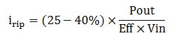
Where irip is the inductor ripple current and IinRMS is the RMS input current of the boost converter below.

The RMS input current is can be quickly computed using below equation
IinRMS = Pout / (Eff x Vin)
Where Pout is the output power, Eff is the efficiency of the boost converter and Vin is the input voltage. You can assume efficiency value of 90-96%. So the inductor ripple current assumption will become
How to Calculate Boost Converter Ripple Current
After selecting devices for the boost converter, the ripple current must be checked. Boost converter ripple current equation is can be derived from the inductor current waveform itself. Meanwhile below is the inductor current waveform for continuous conduction mode boost converter. Familiarization of the waveform, basic operation and the circuit diagram of the boost converter are the keys on how to calculate boost converter ripple current.

Analysis During Ton
Ok, let us now derive the ripple current equation of boost converter. Boost converter ripple current derivation is can be started during Ton (the switch is on). At Ton, the inductor in Figure 1 will charge and by virtue of KVL
Where VL is the voltage across inductor and Vsw is the turn on voltage of the switch. Expressing VL
The voltage induced in an inductor is also defined by below equation
Expressing the change in current di
Substitute VL to the above equation will give
This change in current is only happening from 0 to Ton so we can apply integration to get the magnitude. Then the inductor ripple current equation of boost converter is
Substituting Ton = D x Tsw

Where Ton is the on period of the switch, Vin is the input voltage, Vsw is the turn on voltage of the switch, L is the inductance value of the inductor and D is the duty cycle of the switch or PWM.
Why the limit is from 0 to Ton? From Figure 2 the inductor current is starting to increase from 0 and has its peak at Ton before it is ramping down.
Analysis During Toff
Boost converter ripple current calculation is can also be done by analyzing Toff (switch is off) period, the inductor current will ramp down linearly as shown in Figure 2 above. Performing KVL in the circuit diagram in Figure 1
Where VD is the forward voltage drop of the diode
Take note that during Toff the polarity of the inductor will reverse that is why from the KVL its sign is positive. If we review the basics, inductor will resist in a sudden change of current by producing a reverse or kickback voltage.
Expressing VL from the above equation will give
Then again using the definition of the inductor voltage below
Then expressing the change in current di
Substitute VL to above equation
We are interested with the magnitude of the ripple current so we will integrate from Ton to Tsw this time. Then the ripple current equation of boost converter is
Substitute Ton=D x Tsw

[Eq. 1] and [Eq. 2] are the boost converter ripple current equations. You can use either of the two in boost converter ripple current calculation.
You may also interested on these:
1) How to Calculate the Duty Cycle of Boost Converter
2.) Boost Converter Component Selection Template
3. Boost Converter Component Stress Calculation Template