

What is an Optocoupler? How Optocoupler works? These are just some of the questions I have before knowing this device. Opto coupler or opto isolator or photo coupler is an electronic device (a semiconductor) which is commonly used for signal isolation such as the primary and the secondary of a switching power supply. Its input circuit is a light source which is commonly a light emitting diode (LED). On the other hand, its output circuit is a photo transistor. A photo transistor is a type of a transistor that detects light to establish an operation point. If a conventional BJT needs a base current to operate, this device needs a relevant light intensity to establish a current transfer from input to output. The light intensity is dependent to the forward current of applied to the light source (LED). Some people are calling the light source of the input circuit as the emitter while detector for the output circuit or the photo transistor.

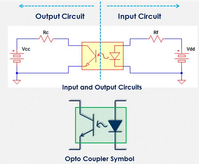
- Figure 1: Above figure is the typical input/output circuitry. The lower figure is the schematic symbol of an optocoupler.
The current to take note in the input circuit is the forward current or the LED current while collector current for the output circuit. The forward current and the collector current are linked to each other through CTR; a short for current transfer ratio. Actually the question how optocoupler works is can be answered by familiarizing the CTR equation. CTR is defined as the ratio of the collector current to the forward current as below
- Eq. 1
(as BJT has its beta = Ic / Ib).
The same with a BJT, optos can be operated at cut-off, saturation and linear mode. At cut-off the device is simply not functioning. There is no enough current to make the LED gives off light and establish an operating point. The collector-emitter voltage will be the same to the level of the collector supply if referring to the above circuit.
When operating in the saturation region, the collector current cannot increase anymore despite there is an increase in the forward current. During this time, Eq. 1 is no longer valid to compute for the collector current. The collector current will only be dependent on the output circuit. The collector-emitter voltage will be equal to the saturation voltage of the device. At saturation the collector current of the above circuit is
VCEsat is very small thus the current limiting factor is only the collector resistor Rc.
In linear operation on the other hand, the collector current will always follow the forward current through a constant factor which is the device CTR specified in the datasheet. At this operation, the collector-emitter voltage is less than the collector supply but higher than the device saturation voltage. The collector current for the above circuit is can be expressed as
Unlike BJT which has three currents to consider; the base, collector and the emitter current, optocooupler has only two. These are the forward and collector current only. The forward current is the level of current needed to establish a sufficient light intensity. The higher the forward current, the more intense the light and the higher the CTR. However, there should be a limit. Too high forward current which results to a high intensity light will shorten the life of an optocoupler. To know more on how to prolong the life of an optocoupler, read this.
The collector current is the current that will flow to the collector and the emitter of the photo transistor. In BJT, the emitter and collector current is a different parameter but in optocoupler these two are the same. It is because there is no electrical connection between the base-emitter or base-collector. This makes the analysis easy and straight forward.
Optocoupler is very useful in switching power supply feedback circuit. Its role is to provide isolation between the output and the input since the two has different ground reference. For detailed explanation on how to analyze optocoupler in a feedback network, click this. Optocouple is can be used also in isolating digital signal to the power signals to avoid false triggering.