

There are several ways how to know if a transistor is saturated or not. It is very important that if you design a transistor to function as a switch that it should operate in the saturation and cutoff. Operation at cutoff is simply interrupting the bias of the transistor. However operating at saturation is not that easy. You need to do some computation, measurements or simulations so that the chosen circuit values are indeed able to saturate the transistor. Likewise, when using a transistor to be operated as a linear circuit or amplifier, the operation must be set within the active region. Setting into active region also demands effort and analysis. In this article I will share to you the methods or ways on how to know if a transistor is saturated or not.
How to know if a Transistor is Saturated – Through Actual Testing
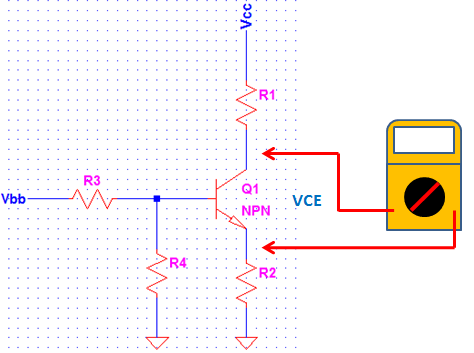
You can conclude the operation of a transistor if it is saturated or not by doing actual measurement. Monitor the collector-emitter voltage of your circuit with a DMM. If the reading is below 0.3V, the transistor is at saturation. Transistors are having saturation voltage range from 0.7V and below but for a circuit designed for hard saturation, the VCE will be lower. Figure below is the setup on how to measure the collector-emitter voltage of a transistor in circuit.
This method is not practical at all. How about you are just started the project, don’t tell me that you will build an actual circuit then measure the VCE and you do this to all the circuits that has BJT in your project? This will have no sense. And aside from the effort and the time spend this approach is also expensive. You need to buy bread boards, wires and other accessories out there. However, if you are already in the verification stage of your product development, yes you can do this approach because intentionally you have to build an actual circuit during this stage.
How to know if a Transistor is Saturated – Through Simulation
This makes more sense than the first method. By doing simulation you can determine the operation of your circuit. You can put a voltage probe across collector-emitter and then run the simulation. The problem with a simulation is that not all the type of transistor is in the library and with available model. Supposing you are only utilizing a freeware circuit simulator like LTSpice, still you need to make a model of the transistor if not in the built in model library. Building model is not simple for anyone that is first time on it.
The same problem with commercial circuit simulator, if the model is not available you need to build your own model. Some circuit designers are using only the available transistor model in the library however this will not really give the exact result.
How to know if a Transistor is Saturated – Through Computation
This is the old school approach which doesn’t need money and has no limitation like model availability. All you have to get is the datasheet of the device. However, I will tell you the disadvantage of this approach this early; this will need knowledge in electronics and analytical skills. But do not worry, I will teach you how.
There are two ways on how to know if a transistor is saturated or not. The first technique is by assuming that the circuit operation is at saturation. The second method is the other way around; assume that the circuit operation is linear.
Method 1: Assume the Circuit is at Saturation
With this method, we are going to initially assumed that the circuit is saturating. Then we are going to solve for the circuit maximum gain or beta then compare it to the device minimum current gain. If the computed maximum circuit beta is less than device minimum beta, yes the assumption is correct; the transistor operates at saturation. Otherwise, it is operating at linear mode.
Example 1:
Let’s apply this technique in a circuit below.

Step 1. Solve for the collector current
Since we are going to assume that the circuit is at saturation, the collector current is only dictated by the value of the collector resistance Rc.
You can include the saturation voltage value of the transistor if you want by getting it in the datasheet. If you do so, the collector current will be
VCEsat is ranging from 0.7V and below depending on the transistor. The advantage of not considering the collector-emitter saturation voltage is that you can include the worst case. You know why later so keep on reading.
Step 2. Compute for the Base Current
Since the value of Vbb is 10V, the base-emitter junction will be surely forward biased and the base current is
(The VBE for BC817-25 transistor has a typical value of 0.7V)
Step 3. Solve for the Circuit Gain (Beta)
Step 4. Compare the Circuit Beta to Minimum Device Beta
For BC817-25 transistor, the minimum beta is 160. Therefore the maximum computed beta is very small than the minimum device beta, no doubt the transistor is operating at saturation.
Now, let us go back to the point why not including the device VCEsat is beneficial. Go back to the judgment, the transistor will saturate if below relationship will be true:
If not including the VCEsat, the computed circuit beta is really the maximum one. If the criterion is true without VCEsat, no doubt that it will be true with the VCEsat. Without including the saturation voltage will not increase the BOM cost, yet it can provide margin to the design.
Verifying through Simulation
From the simulation result, the VCE is around 16mV only. For BC817-25 transistor a VCE reading of below 700mV is already considered saturation. Meanwhile, the collector current is around 20mA.

Example 2:
Using the same circuit but change Rb to 200kΩ.
Step 1. Solve for the collector current
Step 2. Compute for the Base Current
Step 3. Solve for the Circuit Gain (Beta)
Step 4. Compare the Circuit Beta to Minimum Device Beta
Based from the result, above criterion is not meet because 438.596 is greater than 160. Therefore, the transistor is not saturating (linear operation).
The computed beta is greater than the transistor beta. In actual circuit, is this possible? The answer is not. When a transistor is operating at linear mode the circuit beta will always follow the device current gain specified in the datasheet. The computed 438.596 is just the result of the circuit values and conditions we provide. Remember that we assume that the circuit is operating at saturation, by using saturation current the required beta is very high and with this the transistor needs to operate in the linear region to avoid reaching that current and maintain a particular current gain.
In the above method we used the minimum device beta as a comparison. The device beta has a wide range as specified in the datasheet. For example a BC817-25 transistor, the current gain range is 160-400 usually. So why not using in between values or 400? Let me answer this way; when your computed circuit beta is 200 and then you compared it to 400 then the criterion is still true and then you conclude that the transistor is saturating. However, if the actual component beta for the batch of transistor is at the minimum limit (160), then your design will be in trouble. Your circuit operating at active mode rather than saturation as expected. So by using the minimum beta, all the gray areas will be eliminated.
Verifying through Simulation
From the simulation result, the VCE is around 4.6V which is higher than the VCEsat of any transistor. No doubt the circuit is in active mode. On the other hand, the collector current is around 15mA. This is the actual current on the circuit with active operation. The collector current that we computed above which is 20mA is not the actual current since the circuit is not operating at saturation.

In this method, when below criterion is true, the computed collector current is the actual circuit collector current. If otherwise, the computed collector current must be recomputed using linear analysis.
Linear analysis is the one we usually do in college by which we compute the collector current using the given device beta. This analysis will be covered by method 2 below.
Method 2: Assume the Circuit is Operating in the Linear Region
In this method we are going to assume that the operation of the transistor is linear. If the circuit is really operating in the linear region, below criterion must be true:
Example 3:
Using same circuit with Example 1 (redrawn below), determine the circuit operation using method 2.

Step 1: Compute for the Base Current
Step 2: Compute for the Collector Current
Since here we assume that the operation is initially linear, the collector current is to be computed using the device beta. At linear operation, the circuit beta is dictated by the device beta. And also, we are going to consider now the maximum device beta since this can give the maximum collector current. Let us use 300 for the device beta.
Step 3: Compute for the Minimum Circuit VCE
Step 4: Compare the Minimum Circuit VCE to the Device VCEsat max
-2770V is far below than the maximum VCEsat of BC817-25 which is around 0.7V. Below criterion is not satisfied. Therefore, the transistor is saturating.
I want to mention this. The actual circuit VCE cannot be negative because the circuit does not have negative supply. The negative value will be clamped to the ground level which is zero volts. The computation results only tell how saturated the circuit is.
Why used the maximum device beta this time? It is because it can give a maximum collector current and the computed circuit VCE is the minimum value. I you are going to use the minimum beta or any values in between the min and max range, it will create a shade of doubt. When you are going to use the minimum device beta and then you get a circuit VCE of 1V for instance. Then you will conclude that the criterion is true and the circuit is indeed operates at linear region. How about if the actual device beta is residing in the upper limit, the circuit VCE will go below 1V and enters the saturation region.
Example 4:
Using same circuit with Example 3 but change the value of Rb to 200kΩ, determine the circuit operation using method 2.
Step 1: Compute for the Base Current
Step 2: Compute for the Collector Current
(device beta is 300 as used in example 3 above)
Step 3: Compute for the Minimum Circuit VCE
Step 4: Compare the Minimum Circuit VCE to the Device VCEsat max
The minimum VCE of the circuit is still higher than the maximum saturation voltage of the transistor and below criterion is meet. No doubt the circuit operates in the linear region.
Since the circuit is operating in the linear region, the computed collector current is the actual circuit collector current considering the beta is still 300. When you do simulation, the device model uses the typical value of beta which is within the min and max range, so you may get a slightly different result with the above collector current and VCE. If you manage to get the typical device beta then use it in the analysis above, you will make the simulation and computation the same.
Summary
There are different ways on how to know if a transistor saturates or not. Select from these methods which you think the easiest for you. The computation method is maybe difficult for you especially when you are just starting in the design industry. However, if you use it often it will become very easy for you. The advantage of the computation method is that you can consider the worst case thus you can guarantee a high quality product and a reliable and robust design. You will not need also simulation software and build a model on the transistor you use. You will not need to build a prototype to measure the VCE as well thus saving time and money.
There is a design template or calculator that can able to compute the circuit currents, power dissipations, stresses and determine the operation mode of the transistor if saturation or linear.
This circuit design template is very versatile. Try these templates BJT Voltage Divider Bias Design Template and NPN Transistor Fixed Bias Circuit Design Template.
Nice explanation. I have one doubt, which is in the example 1 if I replace the Resistor Rc with one IC then how to calculate if transistor is in saturation state or not.
You need to know the equivalent resistance of the IC then follow the same process.
Great Learning …!!!
Hey man… seriously awesome explanation. I have a habit to look a bit too far into my college course materials and I end up spending hours frustrated trying to understand exceptions or concepts that weren’t really explored. You explained that super well and I can now sleep peacefully.