

PNP transistor is very useful in high side driving. A successful high side driving circuit starts with the proper understanding how to saturate a PNP transistor. Below are the steps to do it.
How to Saturate a PNP Transistor – Step 1
Make sure that the circuit supplies are able to forward bias the emitter-base junction

How to Saturate a PNP Transistor – Step 2
The base current must be high enough

The relationship of Rb and Rc is can be roughly pattern using below rule of thumb.
The selected Rb should not violate below equation in order to avoid device stress.
(IsinkCapability is the specified sink current rating of the microcontroller or any Ic that drive the base of the transistor. IsinkLimit is the set sink current limit so that the pin of micro controller or any IC will not be stressed)
How to Saturate a PNP Transistor – Step 3
Ensure that the computed maximum circuit beta is lower than the minimum device beta specified in the datasheet

Example 1
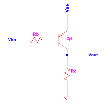
Given values: Vbb – taken from a micro controller unit with a maximum logic low level of 0.3V, Vee – 12V, Q1 – BC807-25, Rc – 2kΩ
Design the circuit in Figure 1 to function as a switch.
Solution:
Step 1: Make sure that the circuit supplies are able to forward bias the emitter-base junction.
The level of Vee is 12V while the maximum level of Vbb is 0.3V, no doubt the emitter-base junction will be forward biased.
Step 2: The base current must be high enough
The value of the collector resistor is defined, so we can use below rule of thumb;
So Rb is
Then check if the value of Rb is still safe for the micro controller. Microcontrollers sink current are ranging from 4mA-16mA, however there is no specified particular value so we will use the minimum. Then,
The actual current that will flow to the micro controller pin is
(IsinkActual is not equal to Ib at all times. It happens only that there is no base pull up resistor on the circuit.)
So, the actual sink current is still less than the 3mA limit. The value of Rb is well suited on the circuit.
Step 3: Ensure that the computed maximum circuit beta is lower than the minimum device beta specified in the datasheet.
It’s checking time. We will compute for the maximum collector current. The maximum collector current is happening when the device is operating at saturation. The maximum collector current is
VCEsat is set to zero to get the maximum collector current since this is the objective.
The maximum circuit beta is
For BC807-25, the beta range is 160 to 400, therefore below criterion is true and no doubt the transistor saturates.
This is very important; in this example the level of Vee is 12V while Vbb is derived from a micro controller. MCUs (short for micro controller units) have a logic high level of 5V. 5V is still lower than the level of the Vee which is 12V. Therefore when you command the MCU to output logic high for the purpose of turning off the transistor, the transistor will not turn off because the emitter-base junction is still forward biased.
Example 2
Provide values to make the circuit below a high side switch.

Given values: Vbb – taken from a micro controller unit with a maximum logic low level of 0.3V and 9mA sink current, Vee –5V, Q1 – BC807-25
Solution:
Step 1: Make sure that the circuit supplies are able to forward bias the emitter-base junction.
The level of Vee is 5V while the maximum level of Vbb is 0.3V, no doubt the emitter-base junction will be forward biased.
Step 2: The base current must be high enough
The value of the collector resistor is not defined, so we can assume it to be 1kΩ. In assuming collector resistor the consideration is the collector current rating of the transistor. In this case the Vee is only 5V so it is safe to assume 1kΩ since BC807 has 500mA typical collector current rating. In application like power supply, efficiency is also a determining factor. Keeping the value of Rc low will give lower loss and a better efficiency.
So, with the assumed 1kΩ resistor, the value of the base resistor Rb is then
In the circuit schematic in Figure 2 the value of Rb2 is usually high enough and almost has no effect in the circuit. The purpose of this resistor is only to ensure that the base of the transistor will not float if ever the Vbb is derived from a circuit that cannot provide logic high. In order to turn off the PNP, the base must be at least equal to the level of Vee. By letting the base floating, noise can trigger the transistor on. Here we can assume 20kΩ resistor for Rb2 (rule of thumb is 10 times the value of Rb).
Then check if the value of Rb is still safe for the micro controller. The sink current of the MCU is given as 9mA. Then the maximum sink current must only be
At this time the level of the base current and the sink current is no longer equal.
The base current is the difference of the current of Rb and Rb2. The current in Rb2 is
The current through Rb is
The base current is
The sink current is equal to the current in Rb.
The actual sink current is less than 75% of the 9mA so the selected base resistor Rb is suited in the design.
Step 3: Ensure that the computed maximum circuit beta is lower than the minimum device beta specified in the datasheet.
The maximum collector current is
The maximum circuit beta is
For BC807-25, the beta range is 160 to 400, therefore below criterion is true and no doubt the transistor saturates.
Important to take note:
In the circuit in Figure 2, the value of Rb2 should be high enough so that it won’t affect the circuit normal operation and the rule of thumb is still valid.
Another Circuit Variation
Circuit below is another circuit variation possible for PNP. However, the addition of Re is no longer necessary if the functionality of the circuit is a switch. This resistor makes the biasing complicated. The circuit can still be driven into saturation but the analysis is somewhat complicated. In switch design, this is not popularly used. Figure 1 and 2 above are the practical circuits for PNP switches.
