
I remember when I started to study matlab I was searching for matlab control design step by step tutorials but I have not seen any. Self studying is not easy, it took me sometimes to learn and get what I want. However, we will not having the same experience. I am about to share to you matlab control design step by step tutorials.
In this tutorial I use R2011a version of matlab. Higher version of matlab has different appearance or interface but the command/syntax are all the same. You may just need a little exploration but do not worry this software is user friendly.
These are our objectives in this tutorial:
-Phase margin Open Loop = 75º +/-3% -Gain margin Open Loop = 24 dB +/-2% -Rise time = 0.5 to 1.5 sec -Settling time = 2.5 sec maximum -Overshoot = 1% maximum
Given Parameters:
Gd1 = 0.008723/(z -0.9892) Gd2 = (0.00845z – 0.005644)/(z -0.9892) Ts = 0.001 sec
Gd1 and Gd2 are the transfer functions of the plant that we are going to control the response. The transfer functions are define in the z domain or discrete format. In this article let me combine the two plant transfer functions (series combination) to obtain a single one. We will convert also the transfer function of the plant into s domain to pair it with an s domain control as well.
Review on Control System Structure
In this article we are going to discuss control system. For the benefit of everyone especially to those who do not have idea or already forgotten control system, we will be having a short review.
A control system consists of a plant, compensator or a controller, feedback, reference and a summing element.

Figure 1 displays a common control system block diagram. Plant is the system to be controlled such as a motor, switching converter, aircraft wing, robotic arm etc. Controller is the one making the output to be within the specifications. Feedback is the one getting sample from the output and compare it to the reference. This is a negative feedback with a particular gain. Most of the times, the gain is set as 1 (direct feedback) for simulation purposes. Summer is the one processing the difference between the reference and the feedback. Reference is the set target level for the output to stay with.
The given transfer functions in this tutorials are for the plant. We are going to design a controller to attain our set requirements.
Matlab Control Design Step by Step Tutorials

1. Open Matlab Software
If you are using the same version with me (R2011a), all the instructions are applicable to you. If otherwise, don’t worry all the commands and syntax are the same although you may need to do a little exploration.
Figure 2 is the command window of Matlab R2011a.

2. Encoding the Transfer Functions
On the command window, type the following and enter:


The
outcomes must be like these


The command window must display like this after encoding the two transfer functions.

3. Getting a Single Transfer Function
In this tutorials we will consider a single transfer function of the plant by having the two in series. On the command window type below and enter

Once the enter button is pressed this should be displayed in the command window


4. Convert Transfer Function to S Domain
Transfer function Gd is still in discrete form with a sampling time of 0.001 sec. In this tutorials we opt to use the S domain of the plant transfer function to prepare a match controller. On the command window type below and enter.


The result should be like this


5. Loading the SISO Tool to Design the Controller
Finally we already have an S domain plant transfer function, Gc. We will design now the controller and to make this easy we will use the SISO tool. SISO tool is bundle with the control system toolbox . On the command window type below and enter.
>> sisotool
Below windows will appear.


Take note that the “SISO Design for SISO Design Task” is empty this time.
6. Selecting Control Architecture
On “Control and Estimation Tools Manager”, click on the “Control Architecture” to select the architecture type. Below window show up.

F=Input Filter, C=Compensator, G=Plant, H=Sensor/Feedback. By default, the values of F, C, H and G is 1. Be sure to select the sign of S1 to –1 for negative feedback. Select the upper left most control architecture. Click OK after all selections have done.
7. Importing Files from Workspace
On the “SISO Design for SISO Design Task” window, click on File then Import. Below window will appear.

Initially the value of G, H, C and F is 1.
Click Browse on Figure 8 and Figure 9 will show.

From Figure 9 select G on “Import model for” section. Tick Workspace and highlight Gc. Click Import then Close.

The value of G will then become Gc as Figure 10. Then click OK.

After clicking OK of Figure 10, “SISO Design for SISO Design Task” is no longer empty as Figure 11.

To save your work, go to File then Save Session. To open the document, go to File then Load Session.
8. Tuning the Controller
To start tuning, zoom in the pink square in the root locus editor until the square splits up.

After zooming in

Start tuning by moving the small squares.

To toggle grid, right click on the plot area. To add or delete zeros or pole or whatever, right click on the plot and choose.
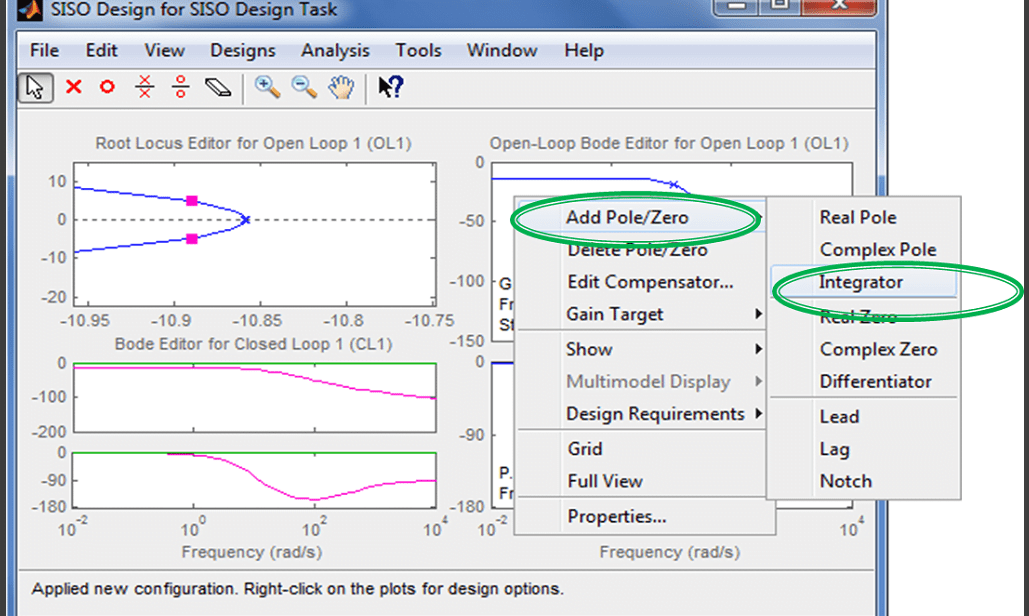
9. Adding Integrator
Since the response is not tunable as it is, we will introduce an integrator. Right click on the plot and select integrator.
After adding an integrator and do retuning, this is now the response.

The open loop bode Gain Margin is 24dB and the open loop bode Phase Margin is 75.2 deg.
10. Viewing the System Response to a Step Command
To view the system response to a step input just navigate to Analysis then Respond to step command. Below figure will appear.

- Blue curve is the close loop response
- Green curve is response from input to controller out
- To select curve, right click on the plot and go to Systems
- Right click on the plot and go to Properties to edit axis limits
11. Checking the System Requirement
Right click on the plot below

Select Steady State, Rise Time, Settling Time and Peak Response.

12. Checking the Compensator Transfer Function

- To create an equivalent Simulink diagram, on the Tool menu of SISO Design for SISO Design Task window, select “Draw Simulink Diagram”
- This is only possible if both the compensator and plant are already exported to MATLab workspace
13. Requirement Versus Result Checking

In this Matlab control design step by step tutorials, the Matlab version used is R2011a. Every year Matlab have two updates usually and may be the version of Matlab you have is the latest one or higher than R2011a. Some of the above steps may be different already. However based on experienced, every update has only small difference and also Matlab is a user friendly software; I am confident that you can still use above Matlab control design step by step tutorials. You may need to do little exploration.