
Once a simulation is made, the confidence level that it will work in actual is very high. This will reduce development lead time and save parts cost for trial and error. Let me share you ACDC linear power supply simulation in LTSpice. For more tutorials, join electronicsconsultation.
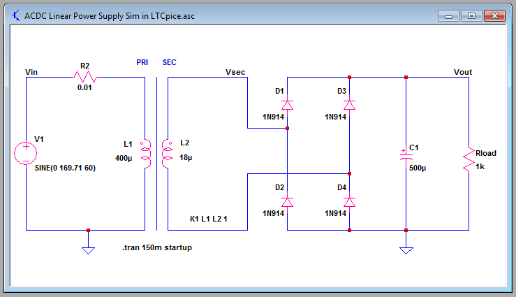
ACDC Linear Power Supply Simulation in LTSpice Template

Download simulation template here.
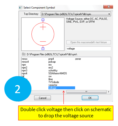
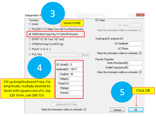
1. V1 – AC supply
How to Set:

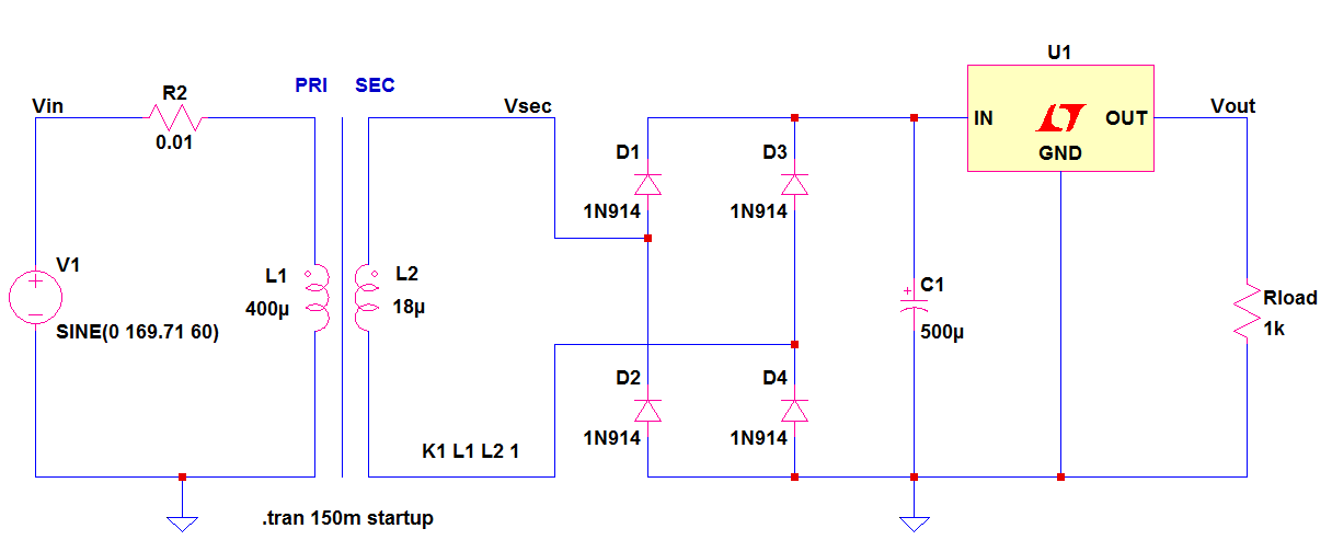
2. R2 – This is the primary winding resistance. In LTSpice, a small resistance in series with the primary winding is needed for the simulation to proceed.
3. L1 and L2 are primary and secondary inductances of a transformer. This is how LTSpice models a transformer. LTSpice does not have an option to enter a turns ratio like other simulators. Instead, the primary and secondary is related through the inductances.
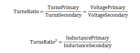
For example:
VinRMS = 120V, VsecPeak = 36V and InductancePrimary = 400uH, the secondary inductance must be

In buying a transformer, be sure it can support the desired frequency, voltage and current rating.
4. Transformer Declaration K1 L1 L2 1
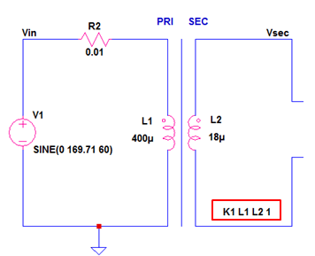
This is the way LTSpice understand a transformer. K1 means a declaration number 1, L1 and L2 and the primary and secondary inductances while the constant 1 is the coupling coefficient. Unity means a perfect coupling. Non-ideal coupling is always less than unity.
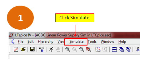
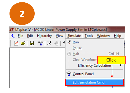
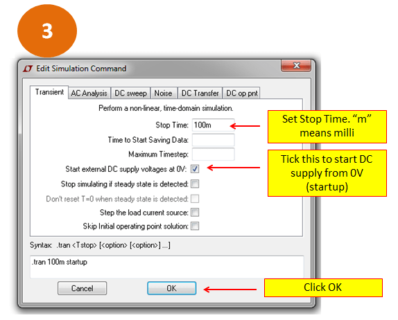
5. Simulation Command .tran 100m startup
This is a transient simulation command. To set, follow below guides.
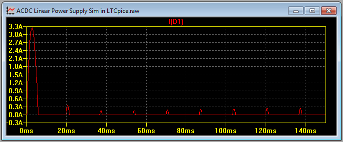
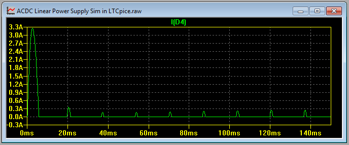
6. D1-D4 comprises the bridge rectifier. A bridge rectifier is preferred because it can give higher RMS voltage and able to use smaller filter capacitor. The critical parameters to take note are current and peak reverse voltage.
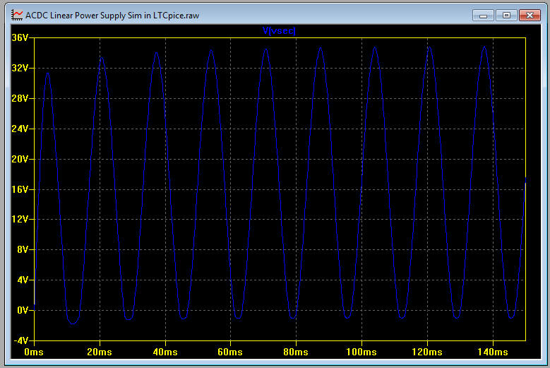
7. C1 is the filter capacitor that makes the pulsating DC to almost pure DC. The critical parameter to take note is ripple current and voltage rating.
8. Waveforms on the circuit model above


9. Adding a Linear Voltage Regulator on the output
A voltage regulator is needed on the output for more precise and critical applications. The most important parameter to consider is the power dissipation of the regulator. The power dissipation of the regulator is just the difference between input and output voltage of the regulator times the load or output current. In below circuit, U1 is a linear regulator. The difference between the voltage on C1 and the output voltage should be not too big to minimize power loss on the regulator. However, do not make the difference very low also because linear regulators have minimum dropout voltage requirement for proper regulation.
Using above circuit, if the desired output is 24V and the dropout voltage requirement of the regulator U1 is 3V, set the voltage on C1 to be around 28V. If the voltage on C1 node is having big ripple, 28V is not be enough. Insure a low ripple on C1 node. The power dissipation of the above linear regulator will be

Supposing the load is 10 ohms, the new power dissipation will be
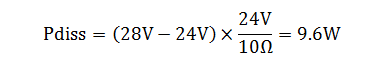
For higher regulator dissipations, use heat sink to cool it off. An external heat sink is preferred. For SMD regulators, make the PCB pad as big and thick as possible.
I hope you enjoy this another tutorial “ACDC linear power supply simulation in LTSpice guide”. If you have inputs, feel free to add comments below.
Excellent tutorial. Searched hard for this one. The LTSpice manual is so vague.
One thing I don’t understand; Why must there be a ground on both side of the transformer? I tried taking it out, and it wouldn’t work.
Doesn’t that defeat the purpose of isolation provided by the transformer?
Also, the circuit won’t simulate if the R2 is omitted and I don’t get why!
Circuit simulators need a ground reference to run. In actual application, you must not put the same ground node to the primary and the secondary so that not to defeat the isolation.
R2 is needed because a voltage source applied directly to an ideal coil (0 resistance) will cause a short circuit to the source.
That makes sense now.
Is the “Parasitic properties : Series resistance” of the voltage source not the same thing as R2?
hi!
i have a question. How can the 0.01ohms resistor withstand a current from -1KA to 1KA? There is no problem with that part of the circuit?
thnks!
1KA current is too high for 0.01 ohm. This will result to a very high power dissipation. But don’t be misguided with the 0.01 ohm resistor I put on the series of the transformer winding. As I mentioned, needed to have a small resistance so that LTspice will proceed the simulation. In reality, the winding resistance could be very low (much lower than 0.01 ohm maybe).
You are the Best ! Better than so many professors with confusing boring and confusing theories
Bonjour, je suis très intéresse par votre description mais je ne trouve pas le régulateur de tension linéaire dans ltspice.
Pouvez-vous me dire comment je dois faire pour avoir ce régulateur de tension linéaire?
Je suis une personne très âgé et je débute en électroniques que je considère comme un mécano moderne, c’est pourquoi j’ai besoin de votre aide!
Hello, I am very interested in your description but I cannot find the linear voltage regulator in ltspice.
Can you tell me how to get this linear voltage regulator?
I am a very old person and I am new to electronics, which I consider to be a modern mechanic, which is why I need your help!
Ferry,
In LTSpice, navigate to component library (you can click the component icon) then go to [Power Products]. Choose which part you like.
Let me know if you still have difficulties.